Polk Boom Bit Battery Replacement

Polk Boom Bit battery replacement guide

Polk Boom Bit battery replacement guide

The Polk Boom Bit is the first wearable Bluetooth speaker to be introduced, allowing you to make calls and listen to music all while having this little speaker clipped to your shirt.  As an antenna man in Perth who is often out on a roof, inside a ceiling or driving from job to job I need to be able to have a reliable speaker I can wear on the go.  Traditional headsets or an ear piece just doesn’t work which can easily get knocked out when using earmuffs or moving around a lot.

Read more ›

Posted in Uncategorized

Why is my TV picture Blurry?

You may often have noticed that some TV channels appear blurry, causing concern as to whether a blurry picture is caused by a TV antenna fault or weak signal. What I can say is that through many years of being an antenna man in Perth, that this concern is becoming increasingly common in recent times.  When customers use our TV wall mounting service, sometimes this is often a subject of concern which we need to explain

When the customer mentions “Why is my TV picture is blurry”, it’s most commonly reported as lack of sharpness around the edges of details, such as the edge of faces, or objects on the picture, and also during times of high picture movement such as when watching the footy when the ball is kicked and the camera pans from one area to another.  It’s quite concerning especially when the display stands at Harvey Norman, JB Hifi and the Good Guys always use the best quality sample videos on the TV you are buying, which simply is not available in most free to air channels that you will watch when you bring that TV home.

You may be asking yourself the Question: what causes a blurry TV picture or TV channels?  – Answer:  A standard definition channel being watched on a TV size that is too big for the room. It’s basically a low quality picture being stretched out on a large display which many people often sit too close to.

Left – Blurry TV picture, not caused by a weak signal or TV antenna issue
Right – Large, sharp, well defined squares, indication of weak signal

Most standard definition channels are broadcast in 576i, this resolution was never designed to be used for TV’s larger than say, 32 inches as that was the most common size TV back in the 90’s and early 2000s. In past times large plasma TVs were very expensive and it was rare for a household to have such large displays. With new LCD, LED and OLED displays becoming much more affordable in recent years, 65 inch TV’s and even larger often in small living rooms is now the norm for most households. The most suitable resolution to produce a sharp picture on these displays is 1080i/1080p (1920 x 1020). Most channels being broadcast in Perth and throughout Australia are still standard definition (576i).

Try this – go to channel 10 while the news is on, watch it for a little bit, and then switch to 10 HD and watch that for a bit.  Switch back and forth between 10 and 10 HD and see what you notice. You will soon come to realize that your TV is too large for how far you are sitting from it, or that you are expecting too much from a standard definition channel for your size TV

So what causes blurry TV channels?  Answer: You have too large of a TV for you room or the channels you are viewing are not high enough in definition for your TV size.

This brings us to the question of – Is a blurry TV channel picture caused by a bad TV antenna or a weak signal?
The answer is no, with digital TV a weak signal does not cause a blurry picture, but rather large, uniform sized and easily noticeable squares, often accompanied by sound disruptions or squeaking in the audio.

The conclusion is, if you’re experiencing a blurry picture on a standard definition channel and you have quite a large display, it’s most likely an unsuitable picture resolution for your TV and unlikely a TV antenna or signal problem.

Posted in Uncategorized

Starlink – What You need to know

starlink dish installed on roof mount

Starlink is a network of over 2000 low orbiting satellites around the earth that provide internet access via the use of a satellite dish pointing to the Satellite.  In 4 years an American company has inadvertently made the troubled Australian NBN network obsolete in many rural areas, offering residents a solution to their internet connectivity needs they likely would otherwise never have.  Especially Starlink will benefit mining and exploration companies, being a game-changer for remote site communications.  As more residents in Perth both suburban and rural are now taking up Starlink internet connectivity there is quite a few considerations that need to be taken and things you need to know.

Will Starlink work in my area?

To be able to physically access the Starlink network there is two criteria :

1. Your city and suburb has coverage by Starlink satellites, you can check here – www.starlink.com/map

2. You have enough visibility to the area of the sky that the satellites orbit around, they constantly move and the dish tracks to them, download the app “Starlink” and use the “scan for obstructions” feature, then scan the sky

Even the smallest of obstructions can account for noticeable decrease in speed during the period of the day when the dish requires to point itself in the obstructed direction.
Minimizing any potential obstruction is very important.

Starlink coverage in australia

Who installs Starlink?

Starlink equipment is designed and intended as DIY self install outdoors on the ground.   A stand and cable is supplied which plugs and starts up within minutes with no special tools. Many customers require installation on the roof of their homes which requires specific mounts, adapters, care and consideration to a few factors.  This is done by independent installation companies, not affiliated with Space-X or Starlink.

Will computers and wired devices work?

Current Starlink routers have no ethernet ports, that means you can’t connect any computers or wired devices directly to them.  Straight out of the box the only way to use your Starlink internet services is via any device that has Wifi, such as a laptop, tablet or phone.  An optional accessory called the “Ethernet Adapter” allows you to connect your existing router or modem to your Starlink. This is not included, you need to buy it separately during your signup procedure if you require to connect any wired devices to your Starlink router.  You can purchase it afterwards if it becomes a requirement.

CCTV camera systems and ceiling mounted Wifi extenders also require an ethernet adapter.

The installation service provided by a Starlink installer in Perth is a labour service to carefully mount your dish and run cabling to the required location.  As you have existing devices, often additional cabling or slight modifications may need to be done which is a separate job, or IP address or DNS re-configuration which any IT technician can do, yet in some cases your computers may auto-discover the Starlink router once connected.

Starlink Ethernet adapter diagram


The Starlink Cable

Starlink dishes are connected by a propriety cable that carries both data and power to/from the Starlink dish.  It differs to regular CAT6 cables in that it has it’s own style of connectors. They can be quite fragile, especially when pulling up cavity walls and pushing down conduits.  The standard Starlink cable length is 22.9 meters (75 feet).  This is generally long enough for most houses, however an optional 50 meter (150 foot) cable is available.  As a general guide a home longer than 20 meters with a high pitch roof, is pushing the limits of the shorter cable.

The smaller end (dish side) of the Starlink able head has a maximum diameter of 15.24mm.  Consideration should be taken if it ever needs to fit down a certain conduit on a single brick wall for example or any external ducting.  While the ends are a propriety design, the cable itself internally is a shielded CAT6 cable.  The cable sheath denotes it’s suitability for outdoor use.  The somewhat loose fitting connector at the dish doesn’t quite inspire confidence, yet it’s recessed deep inside the dish pole which is beneficial for shielding against rain.  It’s questionable weather salt spray in windy coastal areas can eventually work it’s way past the seal

Starlink cable head dimensions


Cost and Power Consumption

Service costs vary and are available on the Starlink website, depending on whether it is a residential or business plan.  As of October 2022, monthly charges are $139 with hardware cost of $924.
This cost varies so a good idea is always to check on the Starlink website.

What is important to consider in the cost is that the dish consumes about 20-40 watts during idle conditions, and upto 110 watts during heavy use.  Depending on how often during the day internet is used, this may equate to a $10-$30 a month in electricity use.  In Australia, 240V AC power is used, no DC powering option is available currently.

How long is the warranty? What happens if something fails?

Starlink equipment comes with a 12 month warranty, thereafter it is the customers responsibility to buy any replacement equipment.  Power surges can also effect both the router and dish, at this point one may begin thinking about UPS and surge protectors.  As Space-X is a USA based company, unlike your local internet service provider, no such tech support staff are available to do site visits.  However basic common sense troubleshooting in many cases is enough to identify a fault or by the use of a local independent IT or Comms technician.  The Starlink router and app have inbuilt troubleshooting algorithms built in allowing faults to be detected remotely.  Limited official technical documentation for professionals is available currently, which would be greatly beneficial for troubleshooting onsite in the field as the uptake of Starlink ramps up.

As of October 2022, all support from Starlink to customer is done via a support ticket, phone support is not available.

Is Starlink good for gaming?

Online gaming often not only requires a decently fast internet connection and a latency below 100ms, however latency and consistently of latency or jitter, is most important.  On fast action first person shooter games, a jitter of 20 milliseconds of latency at a critical time could be the difference between your “shoot” click, registering before or after the target on the other side of Australia or an overseas server has actually moved away from your crosshair.  Actual reported experience has been mixed, with certain users reporting they feel little or intermittent problems in their gaming.  Racing or role playing games may not be of any issue, however Starlink may not be the best option for competitive first person shooter gaming if fibre-to-the-premises or better alternatives are available in your area.

Does Starlink interfere with TV reception

To date, very few reports of interference from Starlink dishes when installed appropriately, it’s mostly considered a non issue.  It’s always a good idea to ensure the Starlink dish is installed in such a manner and position, that in any alignment state it’s radiation pattern will not beam toward the TV antenna or it’s signal path.  It’s important to understand that Starlink is often installed in rural areas, some where the existing free-to-air signal strength and quality, while clear and watchable is already near the point of failure.  Any minor changes such as putting an extra device up on the roof may be enough to effect an already heavily compromised signal.  Best practice is required and the use of a field strength meter to test FTA signal quality before and after incase this is a potential concern.  A good condition digital antenna will maximize the preferential signal strength while minimizing chances of interference, as is use of an LTE filter.

A recent test we did in Wellard involved a new digital TV antenna held 50cm away from the Starlink dish, while doing repeated speed tests to simulate the highest throughput possible.  No uncorrected errors or picture break up was picked up on the signal meter at all and no degradation of the signal quality reading was present.  However once the TV antenna was placed directly in the line of sight of the Starlink dish, a strong high quality signal degraded quickly.  What we can conclude from these tests are that the only scenario which we may expect interference is of TV antennas mounted on tall 5+ meter masts which may at some point of the day become in the line of sight of the radiation pattern of the Starlink dish

Can I take the Starlink dish with me?

Starlink dishes on residential plans are geofenced by default, meaning the dish is configured only to work if used at the registered address.  Taking the Starlink dish with you such as on a camping trip would result in the denial of service.  Essentially the reason is to allow each satellite around the world to serve a finite amount of customers as a quality of service measure.  In 2022 Starlink introduced the portability option, which is accessible under “Add Portability” on your account page for an additional fee charged monthly.  No extra equipment is required.  You can disable portability once you return from your trip.  Speeds during use away from your registered address may be slower.

Removing the dish – an important consideration to take is whether your roof mount for your home allows for quick-disconnect and removal of the dish.  As such a pole adapter is required to be purchased separately.  Starlinks pole adapter is somewhat of a low quality, flimsy piece and aftermarket billet aluminum adapters are of a much better quality and appearance

In motion use is prohibited for the standard dish.  Starlinks terms of service specifically mention that use of the service is prohibited while the standard dish is physically moving, e.g while mounted to the roof of a caravan or campervan, while it is in motion.

The newly released high performance dish, which is larger in dimensions is designed and allowed for in-motion use.

What is the difference between Starlink and Starlink Roam / RV ?

Starlink Roam (Formally Starlink RV), by default uses the same equipment as the standard Starlink plan, with a few differences in the plan and service

1. Portability option is permanently enabled, meaning you can travel anywhere and use the service anywhere
2. You can pause your service when you don’t want to use it, to save money.
3. Starlink RV users are on a lower priority, meaning in times where the network has high use and demand, RV customers may receive lower speeds

Is the Starlink router password protected?

No.  By default no password is set and the router is an open unsecured hotspot, anyone nearby can connect to your Starlink router.  It is recommended to set a strong password.

Does Starlink have a Static or Dynamic IP Address?

Residential plans have a dynamic IP address.  Business plans have the option for a static IP address.  A useful check to carry out is to contact your existing service provider and ask them to tell you whether you are on a dynamic or static IP address.

Posted in Uncategorized

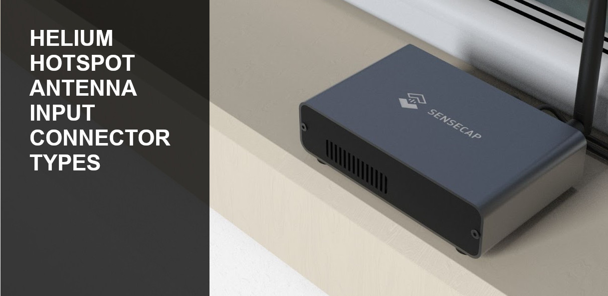
Which antenna plug do Helium miners use?

Sensecap gateway
Which plug does a Helium hotspot use ?  That is what you may be wondering whether you have a Sensecap, Milesight, Nebra, Bobcat or any other brand and are
considering adding an external or remote antenna on your roof

Often when purchasing an external antenna you need to ensure the cable supplied has the correct end on the side that connects to the hotspot.

It can be confusing, as many plugs look very similar.

Pigtials and adapters aren’t exactly cheap, so you want to get the right one

There are a few things to know, and they are important.

Let’s keep this simple, and short as possible

Here is a diagram of three types of inputs you possibly might find at the back of your Helium hotspot.
Now you can see for example, the difference between SMA and RP-SMA
SMA and RP-SMA difference

Different brand and model Helium hotsports or miners will use a different type of input for the antenna.
For example, the Sensecap M1 has a RP-SMA Female input, and the Milesight UG65 has a N Type Female input

Hotspot Input Type on Hotspot Cable connector required
Bobcat (All) RP-SMA Female RP-SMA Male
COTX (All) SMA Female SMA Male
ClodPi (All) RP-SMA Female RP-SMA Male
Sensecap (All) RP-SMA Female RP-SMA Male
Milesight (All) N-Female N-Male
Nebra (Indoor Models) RP-SMA Female RP-SMA Male
Nebra (Outdoor Models) N-Female N-Male
RAK Wireless (All) RP-SMA Female RP-SMA Male
Kerlink (Indoor Models) RP-SMA Female RP-SMA Male
Kerlink (Outdoor Models) N-Female N-Male
LongAP (Indoor Models) RP-SMA Female RP-SMA Male
LongAP (Outdoor Models) N-Female N-Male
Voskcoin (All) RP-SMA Female RP-SMA Male
Mimiq FinestraMiner RP-SMA Female RP-SMA Male
Syncrobit (US/AU) RP-SMA Female RP-SMA Male
Syncrobit (EU) SMA Female SMA Male
Browan MerryIoT RP-SMA Female SMA-Male
MNTD Blackspot / Goldspot RP-SMA Female SMA-Male
Posted in Uncategorized

Perth TV Transmitter Sites and Locations

Myswitch TV map Perth
All TV antennas in Perth receive their signal from a transmission antenna.  These can be located on a tower, or a building and are generally at the highest possible elevation in order for the signal to be radiated effectively across the intended coverage suburbs.  Site locations, licences, and special conditions are regulated by ACMA.  Operators responsible for running and maintaining the transmission equipment and antennas are TX Australia, Swan Broadcasting and Broadcast Australia.  With introduction of television in Perth in 1959, the original transmission site was and is still located in Bickley on Television road, broadcasting Channel 7 (TVW).

Shortly after in 1960, ABC (ABW) began broadcasting from a nearby tower on television road, which also broadcasts SBS beginning in 1986
Nine Network (STW) beginning in 1965 from a site in Walliston on Lawnbrook Road
Network Ten (NEW) beginning in 1988 are transmitted from a tower in Carmel on Welshpool road

List of frequencies from Bickley/Carmel site

Service Name Frequency (mhz) RF Channel Polarization
Seven Network 177.5 6 Horizontal
SBS 184.5 7 Horizontal
Nine Network 191.5 8 Horizontal
Network Ten 219.5 11 Horizontal
ABC 226.5 12 Horizontal

FM and DAB+ services for digital radio are also transmitted from these sites along with mobile services

While all four sites physically use a different tower in independent locations, they are within 1km of each other, and generally known among the trade as the “Bickley” site.
Most of the TV antennas you see on roofs that appear to point to the hills, are receiving their signal from the towers in this site.  With an ERP (Effective Radiated Power) of 82kw, a lot of power is used to transmit the signal throughout the Perth metro area, giving good coverage even to the furthest and newest established suburbs past Alkimos.  A direct line of site can result in perfect reception even upto 200km away, this is in most situations not the case

To alleviate terminal reception problems in certain black spots around the Perth area, re transmission sites have been introduced over the years to transmit the same channels on different frequencies in order to avoid SFN related interference with main transmitters.   The introduction of these sites allow antenna installers alternative sources of receiving a signal.

Scarborough

Introduced in 2013 during the digital switchover, this transmitter is located on top of the Rendezvous hotel, formerly known as Observation City.  The purpose of it’s introduction was to provide a solution to terminal TV reception problems in various areas of Scarborough.  With a very modest low ERP of just 164 watts, coverage was only intended for the suburb of Scarborough.  We have been able to successfully pick up signals and achieve a lock on all channels as far as Padbury.  Due to the transmitter generally having good line of site along the coast, many properties around Trigg, North Beach, and Cottesloe can receive transmissions with the correct antenna, tuning and amplification.  Trouble spots as far as inner Suburbs of Nollamara can receive a perfect signal too due to good line of site.

List of frequencies for Scarborough site

Service Name Frequency (Mhz) RF Channel Polarization
Seven Network 655.5 46 Horizontal
Nine Network 662.5 47 Horizontal
Network Ten 669.5 48 Horizontal
ABC 676.5 49 Horizontal
SBS 683.5 50 Horizontal

Perth City

Introduced in 2013, the Perth City transmitter is located atop of the Bankwest tower on St Georges Terrace.  The unique advantage of a 247 meter height above ground level and a very central location to all suburbs and and unidirectional dispersion of signal gives very good coverage to many areas.  Certain isolated black spots in suburbs close to the metro area can make use of this transmitter around Victoria Park and Burswood where the main Bickley tower is blocked by large apartment buildings.  We have been able to pick this transmitter up as far as from trouble areas like Clifton Hills in Kelmscott, and similar areas in Kalamunda and Gooseberry Hill where there is direct line of site.

Channels and frequencies are the same as Scarborough.

Roleystone

The Roleystone tower is located on Canns Rd, commencing transmissions in 2004 from Seven Network, Nine Network, and SBS and later expanding to inlude ABC and Network Ten.
The coverage of this tower primarily was intended for the suburb of Roleystone, which has many black spot areas where signal from the Bickley/Carmel tower are very weak despite physically being located very close.

Surrounding suburbs and areas can pickup transmission from this tower, notably the Clifton Hills area in Kelmscott.  We have noticed residual signal can be received from as far as south of the river suburbs such as Willeton.  Manual tuning may be required to filter out non preferential frequencies.

Transmissions originally began on the higher end of the UHF spectrum and during the restack moved to lower frequencies.  As such many legacy antennas installed in the early 2000’s may not be optimal.

List of frequencies for Roleystone Site

Service Name Frequency (MHz) RF Channel Polarization
SBS 613.5 40 Horizontal
ABC 620.5 41 Horizontal
Seven Network 627.5 42 Horizontal
Nine Network 634.5 43 Horizontal
Network Ten 641.5 44 Horizontal

Two Rocks

The Two Rocks tower provides coverage primarily to Two Rocks and the signal can be picked up adequately from antennas in Yanchep and Gabbadah.  With the right antenna setup, transmissions can be picked up from the long troublesome area of Seabird which had terminally weak signal.  TV Antenna installations in Guilderton in some instances can use this tower.

List of frequencies for Two Rocks site

Service Name Frequency (MHz) RF Channel Polarization
SBS 529.5 28 Horizontal
ABC 536.5 29 Horizontal
Seven Network 543.5 30 Horizontal
Nine Network 550.5 31 Horizontal
Network Ten 564.5 33 Horizontal

Mandurah/Singleton and  Mandurah/Waroona

Introduced in 2013, the Mandurah/Singleton and Mandurah/Waroona are two separate transmitters located on the same tower, about 10KM east of Pinjarra
Their radiation pattern and intended coverage areas differs, hence the names.  Signals are vertically polarized

The Mandurah/Singleton cell has good coverage spanning from Mandurah to Singleton.
The Mandurah/Waroona cell has stronger coverage south of Mandurah, all towards Waroona.
There is generally a very broad overlap of signal radiation and with the right antenna setup and a combiner it is possible to pick up
channels from both towers in some areas.  Heavy bushland and high trees in various areas effects signal and often high masts are required.

Channels for Mandurah/Waroona

Service Name Frequency (MHz) RF Channel Polarization
ABC 620.5 41 Vertical
SBS 613.5 40 Vertical
WIN Television 634.5 43 Vertical
GWN 627.5 42 Vertical
West Digital Television 641.5 44 Vertical

Channels for Mandurah/Singleton

Service Name Frequency (MHz) RC Channel Polarization
Network Ten 564.5 33 Vertical
Seven Network 543.5 30 Vertical
Nine Network 550.5 31 Vertical
Posted in Uncategorized

SBS HD and Viceland changes to MPEG4

Person watching TV

Are you not able to receive SBS HD, Viceland or SBS World Movies anymore?
These SBS reception problems are most likely due to the switch from MPEG 2 to a newer encoding format, MPEG4.
As an antenna installer in Perth, I often am required to diagnose these issues and explain to the customer that their TV antenna may not be at fault

What is MPEG2 and MPEG4?

MPEG (Motion Picture Experts Group) is an organization that originally developed the most commonly used encoding method
for video, MPEG2 and later MPEG4.  It’s basically a digital method of storing and transmitting video data such as on computer files, DVDs.  This same encoding format is
contained within the signal that your TV antenna picks up

When digital TV was introduced into Australia in 2001, all video streams contained within FTA transmissions were MPEG2, as such most televisions and set top boxes
supplied and sold in the Australian market were able to decode MPEG2 and not MPEG4.  MPEG4 is a newer version of the MPEG encoding format that allows higher compression with similar picture quality.  This allows more channels to be transmitted on the same frequency from the same network, which is important for HD content.

In 2015, the racing channel got introduced that used MPEG4, this was the first channel in Australia to use MPEG4 encoding.  Although it was not very commonly watched,
most viewers had no issue or cause for concern.  Starting from 2017 to 2019, SBS services began to switch from MPEG2 to MPEG4, the exact dates varied throughout different regions of Australia.  This switch happened in Perth in 2019.  Many viewers would come home unable to watch SBS HD, World Movies, and Viceland.  Generally televisions 8 years or older are highly unlikely to be MPEG4 compatible, however it is advised to verify this yourself for your specific TV

How to diagnose the problem

Standard definition SBS channels would still be viewable.  The table below shows all SBS channels and MPEG standard used as of July 2020.
To determine whether your TV is able to receive channels with an MPEG4 stream, go through the following checklist

1.  Perform an automatic channel scan, this has been shown in some isolated cases to work

2.  Check if your TV is able to receive any SBS channels at all including the SD channels, example SBS One (Channel 3).  If you cannot receive any SBS services, your problem is not related to MPEG4 compatibility.  If you can receive SD SBS channels, and cannot receive any of the HD channels 31-32, then MPEG4 compatibility is your issue

3.  Visit your TV manufacturers website and contact the support line with your TV model number to get confirmation.  Ask if a software update is available for your TV as certain models have software updates to enable MPEG4 compatibility

4. Google search your TV model number along with the word MPEG4, example – Samsung UA40H6400 MPEG4.  This may bring up search results that relate to your TV model and MPEG4 compatibility, such as on manufacturer websites, or discussion forums which can often contain helpful answers.

MPEG4 channels perth

If it has been determined that your current TV set is not able to decode MPEG4, a digital set top box can be purchased allowing it to be used to receive both MPEG2 and MPEG4 channels and re-use your existing TV simply as a display.  If you currently are a subscriber of Foxtel using an IQ3 or IQ4 set top box, you can plug your coax cable from the TV antenna outlet into your Foxtel box which will be able to receive all channels, MPEG2 and MPEG4

Posted in Uncategorized

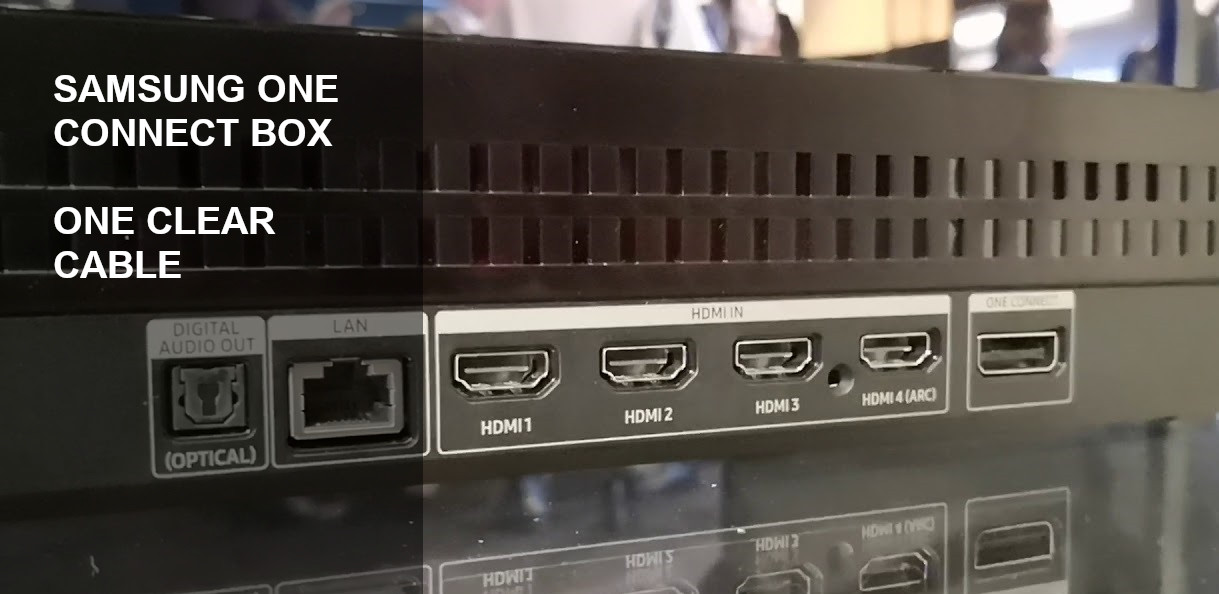
Samsung OCB – One Connect Box and one clear cable

Samsung one connect box
Cable clutter behind a TV wall mount installation has long been an issue both for the installer and the client.  Who would have thought you could combine it all into one.
Samsung has released their One Connect Box, or OCB for short.  Utilizing Samsungs propriety “One Clear Cable” which carries all the required TV signals, power and HDMI signals with one thin slim wire.

You might be left with a lot of unanswered questions about this new technology, such as

– What is the one connect box?
– How does the one clear cable work?
– Conduit size required for the One Clear Cable

What is the Samsung One Connect Box?

Samsung one connect box

The Samsung One Connect Box (OCB) is a central receptacle for all the required signals and cables that normally need to be directly connected to the TV.
This device receives data, power and signals from all the devices normally connected to a TV, and transmits it through one small cable to your Samsung TV.
The inputs vary depending on which year model your OCB box is, however generally available is 240v power input, 4 HDMI inputs, two USB ports, TV antenna RF input,
and digital audio optical input (SPDIF).

What is the Samsung One Clear Cable?

Samsung one clear cableOne clear cable head ends

The extremely thin One Clear Cable has a chipset inside each head, one end modulates all the signals from the OCB  into a data stream that is transmitted
within a fiber optic cable, an astounding capacity of upto 75 gigabits.  The same cable also carries power to the TV most likely via two separate cores.  The voltage used is unknown.
The cable is white in colour which allows it to blend into surrounding walls with a minimum visual impact on TV wall mounting installs

Conduit size required for the One Clear Cable

When doing many TV Wall Mounting jobs in Perth, I have found that the Samsung One Clear Cable often fails to fit through many conduits even after salesman or electricians have guaranteed the customer fitment during the sale of their build or consultation when buying their new TV.  Let’s take a look at the width of the cable head, its about 25mm in diameter.  The conduit we were presented with in this house was a 32mm conduit.  Keep in mind this refers to the outside diameter of the tube.  With the 2mm wall thickness on each side, gives an inside diameter of 28mm.

Samsung one clear cable head width      32mm conduit internal diameter


Given our measurements, a 25mm plug head should be expected to fit inside a 28mm internal diameter of the conduit.  It manages to go in leaving no gaps, then gets stuck.
The problem being is that the head has a thickness of about 13mm.  As the conduit internal diameter is only 28mm as it’s widest, and thinner away from the centre line, causing the edges of the plug housing to get stuck

Samsung one clear cable inside conduit

We notice this cable head has a plastic housing, which with a precision flat head screwdriver were able to gently pop open and remove, exposing the metal shielding that houses the internal chipset.  The removal of the plastic housing makes the cable head much smaller allowing it to now fit into the conduit with ease.  This conduit did have a corrugated bend, which should not be used unless absolutely necessary as the cable head can get stuck in the corrugations on tight bends.

Samsung one clear cable enclosure  Samsung one clear bare shell

We would recommend a 32mm conduit at absolute minimum for One Clear Cables, ideally a 40mm conduit for 100% for guaranteed fitment and no need to remove the cover housings of the plug heads

With a replacement cost of $299 from retailers such as Harvey Norman, this is not a cheap cable and all precaution must be taken not to damage it during wall mounting your TV.  The Samsung one clear cable and one connect box provide a great solution for neater installs and less cabling and solve many traditional problems presented when wall mounting a TV in Perth.

Posted in Uncategorized

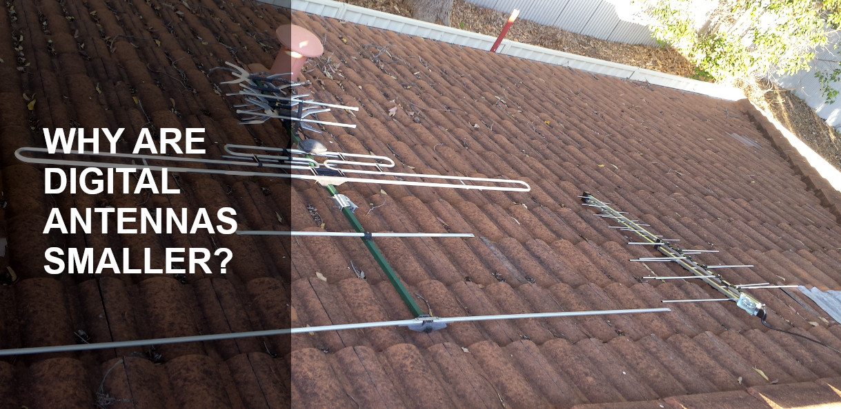
Why are digital antennas smaller?

analog and digital antenna difference
Have you ever driven through a new housing estate or a road with a few newly constructed homes and noticed that digital TV antennas are a fraction of the size
of the old analog antennas?

It’s not to save on manufacturing costs, it’s not by regulation and definitely not by coincidence.
It’s to make them receive a stronger signal.  That’s right, these smaller antennas pick up a stronger signal.

Still don’t believe it?
There’s a science behind it.

Every channel is transmitted from the tower using a different frequency.
For example, in Perth currently digital channels run on frequencies 177.5 MHz – 226.500 MHz

The length of the wave differs for each frequency being used, remember that.

short and long wavelength difference

Let’s calculate the wavelengths, and half wavelengths for the frequencies most common channels received from a TV antenna in Perth.

Each arm of a TV antenna has a different length.  The length of each arm must be a specific length in order to pick up the strongest signal on each different channel.
For most TV antennas, 1/2 the wavelength of each arm is used

For example, the now obsolete analog channel 2 (ABC) ran on a low frequency and had a extremely long wavelength.  In comparison,  the Digital TV frequency for ABC has a very small wavelength

Lower Frequency = Larger Wavelength = Larger antenna arms
Higher Frequency = Shorter Wavelength = Smaller antenna arms.

Channel Frequency 1/2 Wavelength
(Antenna Arm Diameter)
ABC Analog (obsolete) 64.25 MHz 2407 mm
Seven Digital 177.5 MHz 844 mm
SBS Digital 184.5 MHz 812 mm
Nine Digital 191.5 MHz 782 mm
Ten Digital 219.5 MHz 682 mm
ABC Digital 226.5 MHz 662 mm

Analog TV frequencies started as low as 64.25 MHz, where ABC was located, requiring arm diameters as long as 2407 mm
Digital TV frequencies have the lowest frequency on 177.5 MHz, where Channel 7 is located, requiring arm diameters as short as 844 mm.

With digital frequencies being higher, the larger elements of analog antennas are no longer needed.  A smaller “digital antenna” can then outperform a larger “analog antenna” because it’s arm lengths are specifically tuned to the frequencies it needs to receive and at the same time reject any out of band interference.

Posted in Uncategorized

TV Antenna Site Survey

Hills TV antenna on roof

Installing TV Antennas is often can be as easy as pick a location that is the easiest to get to, put the antenna on and hope for the best.
Simple theory is: the towers transmit, the antenna receives, unfortunately reality is never so simple.
RF Signal is not spread equally above all areas on the roof space, and selecting the incorrect location for your TV antenna installation in Perth can result
in a poor signal, especially on Ten and ABC channels which are known to have a lower signal strength. The importance of doing a proper site survey to get the best signal
increases in poor signal areas such as Scarborough, and specific areas around Padbury, Duncraig and Kallaroo.

To conduct a proper site survey, a professional grade field strength meter is used such as from Unaohm or Roversat. Cheaper DIY meters do not produce repeatable results
and no contractor can be in the business as a professional antenna technician without high end measuring equipment, especially when back to back testing is required.
The specific antenna that will be installed for the customer is used. At every point of the roof, we conduct the following tests at 3 different heights

1. DCP (Digital Channel Power), a measurement of the signal strength being received by the antenna

2. MER (Modulation Error Ratio, a measurement of how clean and error free the signal is

3. Slope, a measurement taking into consideration the power of all channels in the band

4. Stability of DCP and MER, a measurement of how stable the readings are over a given period of time.

Without all four of these measurements being taken at many points in the roof before the antenna installation, the customer will never get the best reception possible.
As a step of planning and preparation, a significant amount of time and care is invested in doing this to get the customer the best results,
but also saves the customer money in the long run by reducing the need of costly relocation or modifications down the track which is what keeps
the majority of the TV antenna trade in business.

If there is a specific channel that is very weak in the area, especially one that the customer watches a lot we will often select a location on the roof
that is biased to giving this channel the best signal possible compared to stronger channels. Once the correct location is chosen, we will proceed to install
the antenna and fine tune for the best possible signal, giving you the best quality reception possible.

Posted in Uncategorized

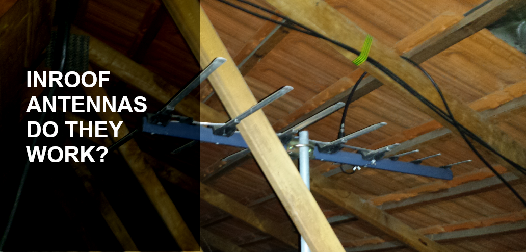
Antennas inside roof space – do they work?

TV antenna inside roof

The age old question that I get asked is – can my antenna be mounted inside the roof space?
Sure, anything can be done, but how good will it work?

While this type of installation is advised against, many customers still find this placement attractive.  While signal is greatly decreased when mounting a TV antenna inside the attic, with a few careful steps this can be done successfully in some cases.

The answer whether in-roof antennas work is not simply a yes or a no, however a varying degree of reception reliability from perfect, intermittent to failure to display
or scan in any channels.  This is all dictated by the available Signal Strength and quality outside and inside your roof

The first fundamental that must be understood is the signal that is available outside your roof, before it is degraded after it penetrates through your roof.
In Perth for example, areas where signal is very strong are Dianella, Morley, Ascot, Midvale, Cannington and Ballajura for example.  The signal strength and quality
in suburbs like this is known amongst installers to be very strong and is able to make it through obstructions such as roof tiles and still maintain an acceptable level
inside the roof space where the antenna will be placed.

In comparison, trouble areas such as Fremantle, Scarborough, Wembley Downs and Claremont have a very low signal strength available at lower heights, which generally
after penetration through roof structure will not provide an adequate signal strength and quality to the antenna inside the roof.

Once the fundamental of available signal strength is understood, we consider the variables that will effect that signal

– Roof Surface – Generally a Tile roof will pass the signal without too much degradation.  Any sort of sarking or insulation under the tiles will heavily degrade the signal strength.
A metal roof will block almost all the incoming signal.  It is only in rare cases where signal strength is very strong that reception is possible, however

– Antenna position – With in-roof antennas, height is a major factor, even small adjustments in height can yield noticeable improvements.  Adjustment is also important so it must be ensured
the antenna can point toward the correct direction of the tower in the proposed installation area.

The conclusive rule of thumb is – An in-roof antenna installation is possible in any suburb that has a very strong signal of 70dbuv and higher available and where the antenna is being installed on a house with a tile roof without any sarking or insulation.

Posted in Uncategorized

Quick Quote